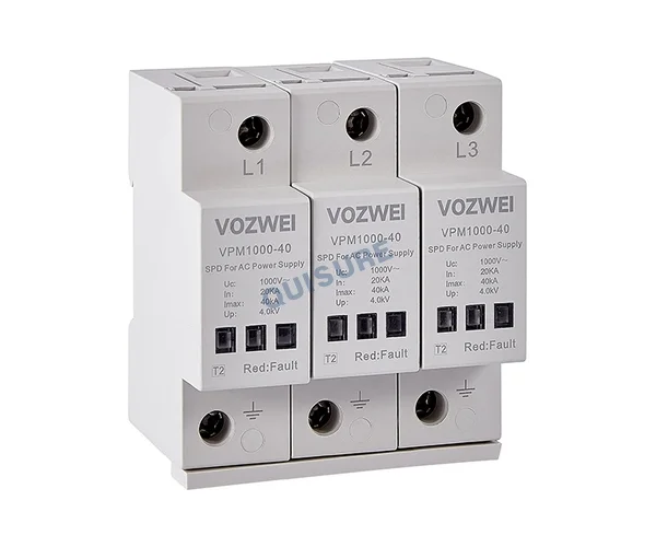
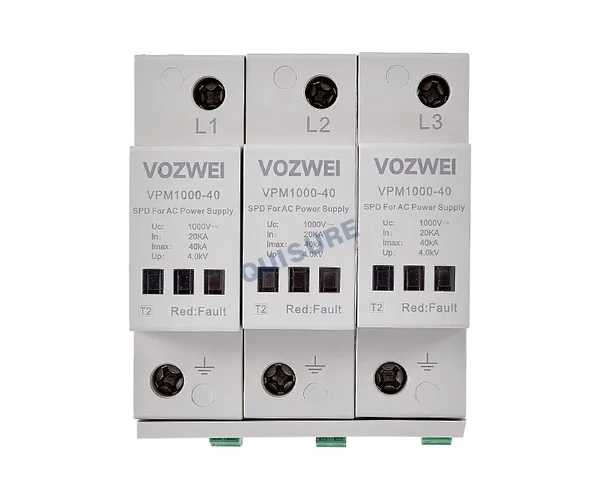
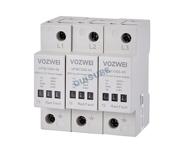


VPM1000-40 Series Type 2 AC SPD, VOZWEI
SPD according to EN/IEC 61643-11: Type 2
Max. continuous operating voltage Uc: AC 1000 V 50/60 Hz
Nominal discharge current In (8/20 μs) : 20 kA
Max. discharge current Imax (8/20 μs): 40 kA
Voltage protection level Up: ≤ 4.0 kV, ≤ 4.5 kV
Application:
This surge protective device (SPD) offers robust performance in diverse grid conditions and is specifically designed for application within new energy systems, including wind power, photovoltaic installations, and EV charging infrastructure. It is engineered for installation at key internal nodes such as converters, inverters, combiner boxes, grid-connection cabinets, and charging piles (typically within LPZ1 to LPZ2 zones). Its purpose is to protect sensitive electrical equipment from damage caused by induced transient overvoltages and switching surges.
Featured:
- Nominal discharge current In (8/20 us): 20 kA / 50 kA
- Max. discharge current Imax (8/20 us): 40 kA / 100 kA
- Max. continuous operating voltage Uc: AC 750 V / AC 1000 V
- Selectable circuit protection modes: 3P / 4P / 3P + 1P / 3N + NPG
- Utilizing high-performance metal oxide varistor (MOV) technology, the device offers high temporary overvoltage (TOV) withstand capability and provides excellent voltage limiting performance
- Modular pluggable anti-loosening structure, enabling simple installation and easy maintenance
Nomenclature:
VP □ □–□/□□
1 2 3 4 5
| SN | Name | Specification, type code |
| 1 | Design code | VP |
| 2 | Product Series | M |
| 3 | Max. continuous operating voltage Uc | 750: AC 750 V; 1000: AC 1000 V |
| 4 | Max. discharge current Imax | 40: 40 kA; 50: 50 kA; 100: 100 kA |
| 5 | Protection mode | 3P: 3P; 4P: 4P; 3P+1P: 3P+1P; 3N+NPG: 3N+NPG |
Example: VPM1000-40/3P → Uc: AC 1000 V; Imax: 40 kA; Protection mode: 3P.
Technical parameters:
| Model | VPM1000-40/3P |
| SPD according to EN/IEC 61643-11 | Type 2 |
| Protection mode | 3+0 mode |
| Nominal operating voltage Un | AC 800 V 50/60 Hz |
| Max. continuous operating voltage Uc | AC 1000 V 50/60 Hz |
| Nominal discharge current In(8/20 μs) | 20 kA |
| Max. discharge current Imax(8/20 μs) | 40 kA |
| Voltage protection level Up | ≤ 4.0 kV |
| Leakage current | ≤ 20 μA |
| Response time | ≤ 25 ns |
| Max. backup fuse | 50 A-125 A gL/gG |
| Cross-sectional area | 6 ~ 35 mm2 |
| Stripping length terminals | 12.5 mm |
| Tightening torque | 3 N·m |
| Normal/Fault Indication | Green/Red |
| Remote signaling mode | RSC: Remote Signal contact, NC-COM-NO contact |
| Performances of remote signal contact | AC: 250 V/0.5 A; DC: 250 V/0.1 A, 125 V/0.2 A, 75 V/0.5 A |
| Remote cross-sectional area | Max. 1.5 mm2 |
| Installation method | 35 mm DIN rail |
| Housing material | UL94-V0 |
| Protection class | IP20 |
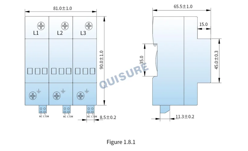
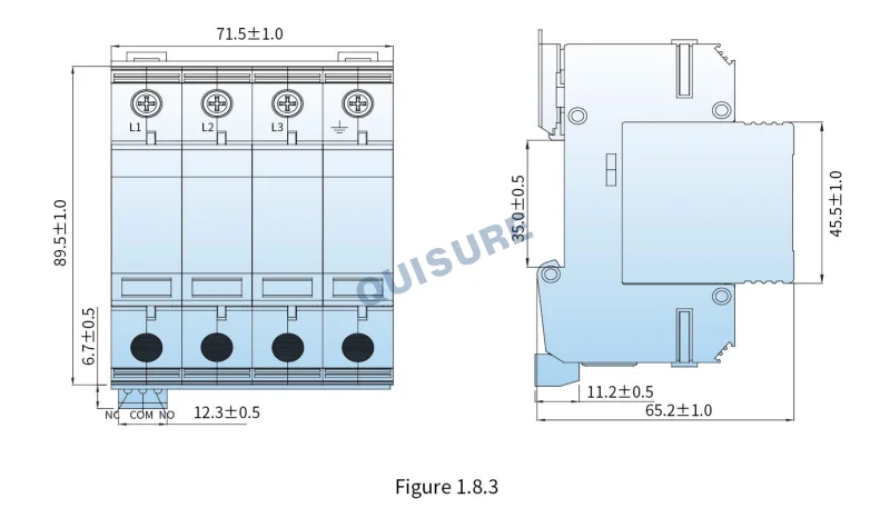
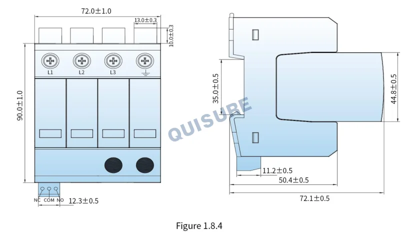
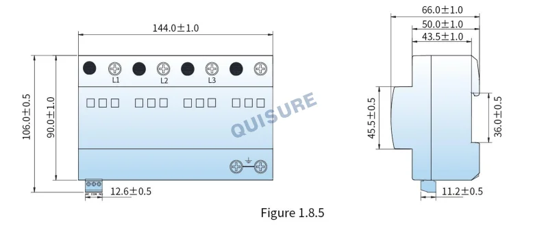
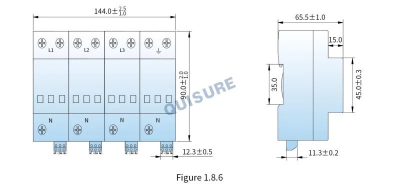
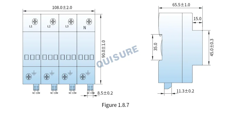
| Outline dimensions (without terminal) | 90 mm × 81 mm × 65.5 mm (tolerance ± 1 mm) |
| Module pluggable | Pluggable |
| Internal protection device | The lightning protection unit has a built-in thermal trip device |
Selection guide:
| Model | Un | Uc | Up | In | Imax | Protection mode | Operating Principle | Size |
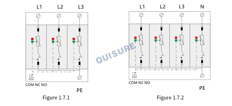
| VPM1000-40/3P | AC 800 V | AC 1000 V | 4.0 kV | 20 kA | 40 kA | L-PE | Figure 1.7.1 | Figure 1.8.1 |
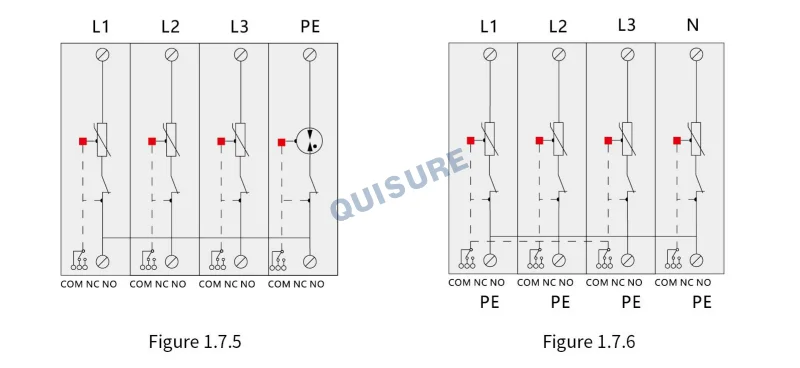
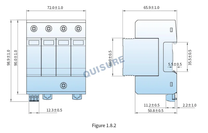
| VPM1000-40/4P | AC 800 V | AC 1000 V | 4.0 kV | 20 kA | 40 kA | L-PE | Figure 1.7.6 | Figure 1.8.7 |
| VPM1000-40/3N+NPG | AC 800 V | AC 1000 V | 4.5 kV | 20 kA | 40 kA | L-PE | Figure 1.7.5 | Figure1.8.6 |
Operating Principle:
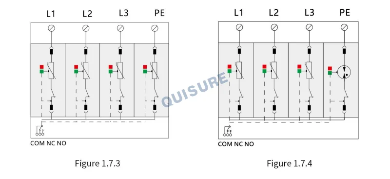
Related products


Quality Controls
Delivery Guarantees
Made in China
Transaction Visualization
No Worries After-sales
Professional Experience