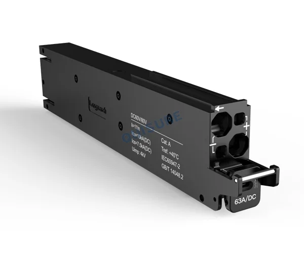


MB8Z-63 intelligent MCB 1P+N, DC60/80V, 6-63A, Icu:10kA for Telecom, QuiSure
Model: MB8Z-63
Rated voltage: DC60/80V
Rated current: 63A
Icu(kA): 10kA
Poles: 1P(Positive through)
Certifications: CCC, CB, CE
Mechanical life: 20,000 times
Electrical life: 10,000 times
Application and Standards
MB8Z-63 series intelligent plastic case circuit breakers (hereinafter referred to as circuit breakers) are suitable for circuits with rated working voltage of DC 60 V / 80 V and rated working current of 125 A and below. This series of products are mainly used in telecommunication equipment rooms and communication cabinets, computer room, or end user lines to provide overload and short circuit protection. It supports intelligent functions, including collecting data such as electric energy, power, voltage, current, temperature, etc., can query data information and set parameter information through RS485 communication, and support four remote functions of power (remote control, telemetry, remote signaling, and remote adjustment).
Executive standard:
- IEC60947-2 Low-voltage switchgear and controlgear – Part 2: Circuit-breakers
- IEC61000-4-3 Radiated, radio-frequency, electromagnetic field immunity test
- IEC61000-4-5 Testing and measurement techniques – Surge immunity test (15kA (8/20us))
Pain Points in the Application Scenario
- Low space utilization: Traditional miniature circuit breakers (MCBs) result in inefficient space usage, severely limiting the expansion capacity of base station equipment.
- Inaccurate energy management: Coarse energy monitoring and a lack of precision in power data make it difficult to meet the demands for granular energy efficiency management.
- Low O&M efficiency: Slow response times and the reliance on on-site personnel for even simple troubleshooting lead to prohibitively high operation and maintenance costs.
- Lack of intelligent control: Without support for scenario-based strategies, scheduled switching, or remote communication, it is challenging to adapt to diverse environments and customized requirements.
Features
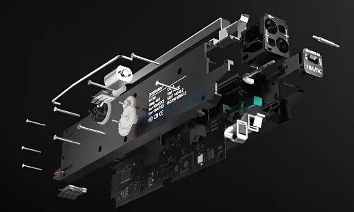
- Adopt a plug-in design supporting hot-swapping and automatic communication address recognition to achieve plug-and-play while reducing intermediate copper bars and joints.
- Equipped with an independent control system that executes protection and actions (e.g., scheduled power on/off) based on preset parameters even without a network or main controller.
- Through hardware platforming and software-defined technology, users can freely customize parameters for over/under-voltage, overcurrent thresholds, delays, over-temperature protection, and auto-reclosing.
- Real-time monitoring of electrical parameters such as voltage, current, power, and temperature, meeting Class 1 meter accuracy (deviation ≤ ±1 %) with interface and internal thermal monitoring.
- Built-in electric drive mechanism supports remote switching, featuring power cabinet position authentication to ensure closing is only permitted upon authorized access.
- Integrate traditional protection, remote control, precision metering, self-diagnosis, and back-up protection, with Ics = 100% Icu =10 kA to meet the smart and reliable energy needs of base stations.
Conditions of use
- Altitude: The altitude of the installation site is not more than 3000 m, and it can be derated if it exceeds 2000 m; Working temperature: -40 °C ~ +70 °C; Working humidity: ≤ 95 %.
- The pollution level of the installation site is level 3.
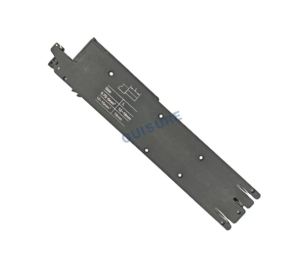
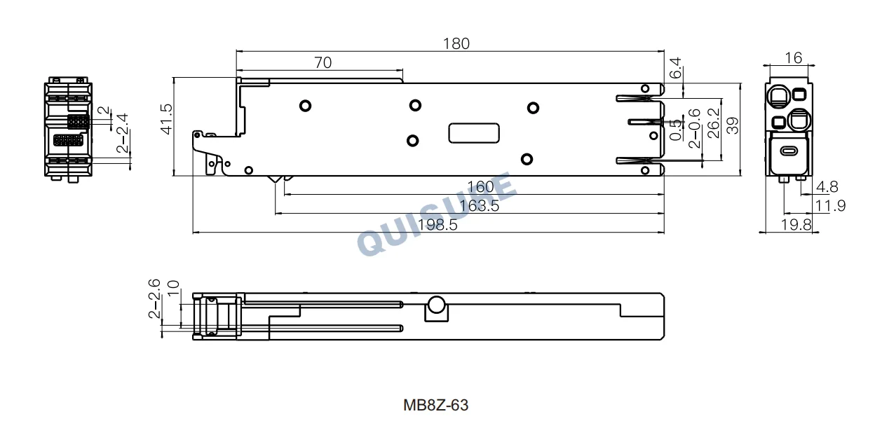
- Plug-in design: The thickness of the rear-end plug-in copper bar is 2 ± 0.1 mm, and the thickness of the communication plug interface PCB board is 1.6 ± 0.1 mm.
- MB8Z set screw clamping (after the Phillips screwdriver screw is unscrewed, the terminal is inserted, and then the screw is tightened to press the terminal).
- Product design meets RoHS requirements.
Specifications
| Model | MB8Z-63 |
| Rated voltage | DC 60 / 80 V |
| Frame current | 63 A |
| Rated current | 63 A |
| Icu (kA) | 10 |
| Poles | 1P (Positive through) |
| Wiring area (mm²) | bare wire: 0.75 ~ 16; With pre–insulated ferrules: 0.75 ~ 10; Without pre–insulated ferrules: 16; 1. Cross–sectional area of cold–pressed end: 1.3 mm ≤ L ≤ 6.2 mm, 1.3 mm ≤ W ≤ 6mm; 2. When the cold pressing end is inserted into the depth of 19mm, the diameter of insulating sleeve or heat shrinkable pipe ≤ 9.5 mm. |
| Line length (mm) | 0.75 ~ 6 mm²: 12 ~ 18 10mm²: 14 ~ 18 16mm²: 18 ± 1 |
| Mating depth (mm) | 17–19 |
| Cold–pressed end length (mm) | 0.75 ~ 6 mm²: 10 ~ 16 10 mm²: 12~16 16 mm²: 16 ± 1 |
| Unipolar insertion force | ≤ 60 N |
| Unipolar pull out frame force | ≤ 55 N |
| Circuit breaker insertion and removal times | ≥ 200 |
| Mechanical life | 20000 |
| Electrical life | 10000 |
| Weight (± 5 %) | 180 g |
Function description
1. Measurement:
Voltage: The measurement range: 0 ~ 80 VDC, accuracy: 0.5 %;
Current: The measurement range: 63 A: 0 ~ 63 A DC; 125 A: 0 ~ 125 A DC, accuracy: 1 %;
Power: The measurement range: 0~10 kW, accuracy: 1 %;
Energy: The measurement range is 0~700000 KWH, accuracy: 1 %;
Contact temperature: -40 °C ~ +150 °C, the accuracy is ± 2 °C;
Internal temperature: -40 °C ~ +150 °C, the accuracy is ± 2 °C;
Switch on-off status and on-off times count.
2. Protection function:
Under-voltage protection: voltage lower than the set value for 10 s continuously, the switch opened, the voltage recovers and lasts for 10 s, switch will automatically closed;
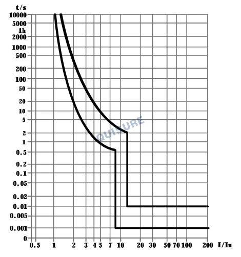
Overload protection: 125 A: 105 % * le will not disconnect within 2 h, 130 % * le will disconnect within 2 h; 63A:105 % * le will not disconnect within 1 h, 130 % * le will disconnect within 1 h; the tripping current and delay time are adjustable;
Short circuit protection: C-curve;
Current-limiting protection: the current is greater than the threshold, and the duration reaches the setting, it will disconnect. When the disconnection time reaches the setting and the number of recovery time counts is less than the setting, it will automatically try to recover.
3. Alarm function:
Overcurrent; Trip; Contact over-temperature; Internal over-temperature; Open at low voltage; Power off; Closing / opening failed; Controller failure;
4. Address :
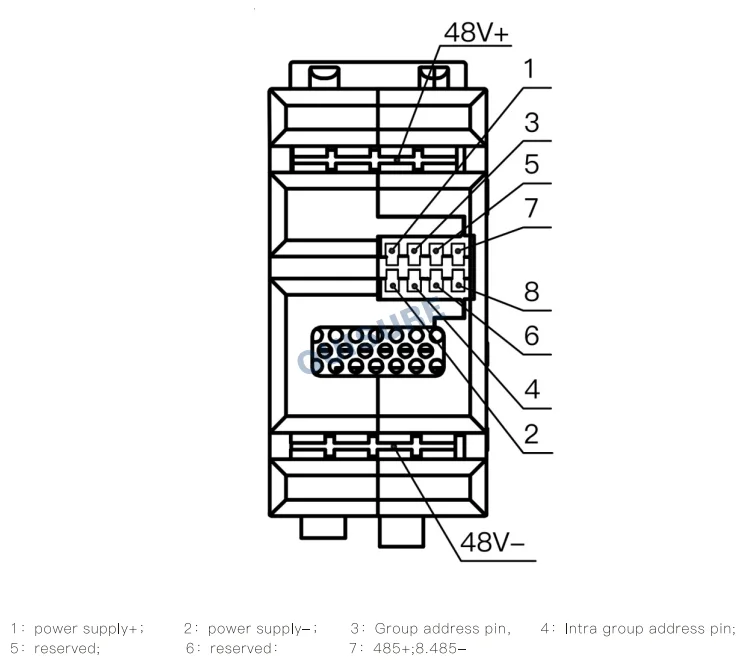
Identification: Automatically identify its own address by detecting the voltage of signal pins 3 and 4,and the host computer communicates with the switch through this address.
5. Authentication:
The product can be closed automatically only after authorization, and the authorization status Invalid after power failure;
6. Anti-misoperation:
It cannot be closed manually or automatically when it is not inserted precisely; it cannot be inserted under the closed state;
7. Control function: the breaker can be opened or closed through the upper computer;
8. Fault opening times: count the opening times caused by overload and short circuit, and save them when power off;
9. Power-off strategy: power-off can be set according to parameters such as voltage value, time, and energy;
10. Anti-reverse connection: the equipment will not be damaged after the product is reversely connected;
11. Alarm: set alarm according to current, voltage, temperature, opening and other information;
12. Parameter setting:rated current, power-off voltage, recovery voltage and other parameters can be set;
Tripping characteristic curve
Instantaneous tripping range
DC: Instantaneous tripping range 11In(1 ± 20 %)
Outline and installation dimension
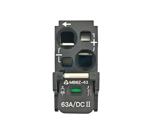
Connecting terminal definition
Derating factor table
| Altitude | Working current | Working voltage | Power-frequency withstand voltage | Uimp | Short circuit breaking capacity and electrical life |
| 2000 m | In | Ue | 1.00 | 1.00 | 1.00 |
| 3000 m | 0.99In | Ue | 0.89 | 0.89 | 0.81 |
| 4000 m | 0.96In | Ue | 0.80 | 0.80 | 0.71 |
| 5000 m | 0.94In | Ue | 0.73 | 0.73 | 0.63 |
| Rated current | -40 ℃ | -30 ℃ | -20 ℃ | -10 ℃ | 0 ℃ | 10 ℃ |
| 63A | 1 | 1 | 1 | 1 | 1 | 1 |
| Rated current | 20 ℃ | 30 ℃ | 40 ℃ | 50 ℃ | 60 ℃ | 70 ℃ |
| 63A | 1 | 1 | 1 | 0.92 | 0.84 | 0.78 |
Installation and maintenance
- After unpacking, the user must check whether the equipment is in good condition, whether the leaking metal parts are rusted, and whether the product is defective due to poor transportation and storage. If the above phenomenon occurs, the product cannot be used, please contact the supplier in time to solve
- Check whether the technical parameters on the product shell meet the requirements for use.
- Installation operation and precautions:
1) Before inserting the circuit breaker into the cabinet, make sure that the circuit breaker is in the open state (otherwise, it cannot be completely inserted into the cabinet);
2) Insert the guide rails on both sides of the circuit breaker along the cabinet guide rails, and push the circuit breaker into the cabinet as shown in the figure below;

3) As shown in the figure below, after the circuit breaker is completely inserted into the cabinet, the circuit breaker buckle will protrude from the card slot of the cabinet; before connecting the front-end cable, use a screwdriver to unscrew the set screw, and then insert the cable of the corresponding specification into the cable interface, then the screwdriver tightens the set screw, the cable is clamped, and the front-end cable connection is completed;
As shown in the figure below, the circuit breaker has just been inserted into the cabinet (simplified) state view
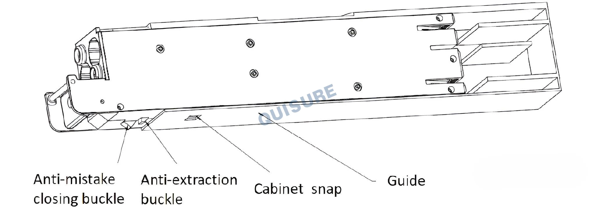
4) Press the button to close the circuit breaker, pull out the button to open the circuit breaker;
5) When the circuit breaker needs to be taken out, first open the circuit breaker, use a screwdriver to unscrew the screw from the front terminal to take out the cable, and then continue to pull the button (the buckle is automatically unlocked, the rear copper bar of the circuit breaker is separated, and the circuit breaker removed from the cabinet.
Note:
plug-in installation, the thickness of the rear-end plugged copper bar is 2 ± 0.1 mm, and the thickness of the copper bar of the communication signal port is 1.6 ± 0.1 mm;
- The overload characteristic of this circuit breaker is set by the manufacturer and cannot be adjusted at will during use to avoid affecting the performance.
- The cross-sectional area of the connecting conductor is compatible with the rated current of the circuit breaker (see the table below).
| Rated current (A) | 63 |
| Conductor cross section (mm) | 16 |
Related products


Quality Controls
Delivery Guarantees
Made in China
Transaction Visualization
No Worries After-sales
Professional Experience